Configuring Microcontroller
I need to configure the clocks of the microcontroller to allow for transmit and receiving while also processing and displaying information
Differential Output
SAE J1850 PWM needs a differential output where a low logiv is less than 2.2 volts and a high is larger than 2.8V.
Moreover, this is a single half-duplex channel.
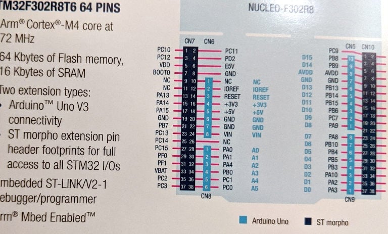
I needed to configure 2 pins to output the J1850 PWM and then switch over to inputs to read the incoming PWM.
Service title
Write a short text about your service. Highlight key benefits for potential clients.
Setting Up SAE J1850 PWM Timer
The clock on my STM32 is 64MHz and 16 bits. My desired timer rate is 124.8kHz.
Taking a ratio of the two, I get 512.8 as my count period. Since 513 is less than 65535, I do not need a prescaller. The actual clock rate I get is 124756Hz which is pretty close.
Level Shifting
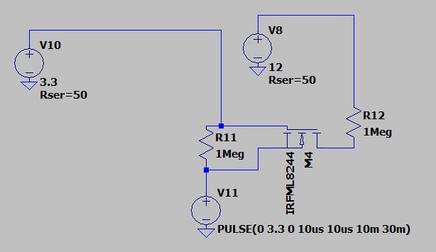
The STM32 outputs at 3.3V and can handle up to a 5V input on the GPIO pins. A HIGH logic in J1850 is greater than 4.5V, and a LOW is less than 3.5V. I will need a dual directional level shifter.
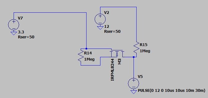
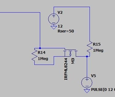
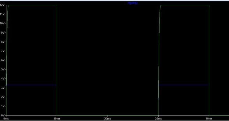
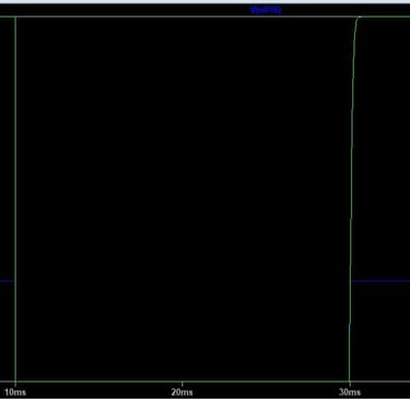
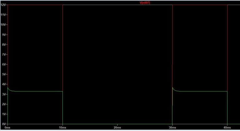
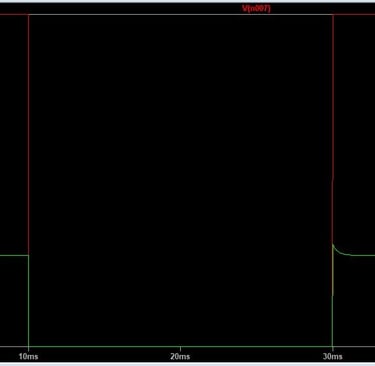
12V 100KHz pulse being shifted down to 3.3 has a small overshoot that hits 3.5V. 3.3V 100KHz pulse being shifted up is damped due to the rise time and reaches 12V at the rise time.
This design draws less than 2mA from the Neucleo board's 3.3V line. In future iterations of the project,
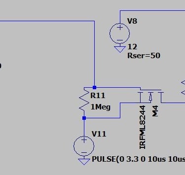
I looked at several MOSFETs for this design. I settled on the IRFML8244 as it provided a low offshoot, has a high switching speed, and they are $3 for 10.